Product information
- Catalogs and Download
- Product data, catalogs, and instruction manuals can be downloaded from the member site.
※ Membership registration is required.
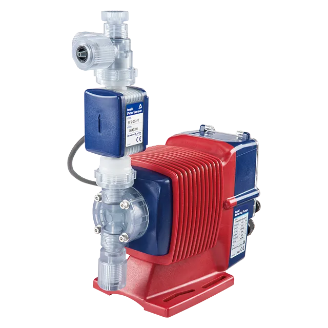
Max. discharge capacity range: 38 - 420 mL/min Electromagnetic metering pumps with precise flow monitoring, feedback & control
※In order to download information materials and catalogues, you need to register a user
account (for free) with us. Membership Registration
| Max. discharge capacity range | 38 – 420 mL/min |
|---|---|
| Max. discharge pressure | 0.2 – 1.0 MPa |
| Main materials | PVC, GFRPP, PVDF, SUS316 |
| Stroke rate | 1 – 360 spm |
| Power supply | 100 – 240 VAC 50/60 Hz |
| Liquid temperature range | PVC type: −10 – 40˚C GFRPP type, PVDF type, SUS type: −10 – 60˚C |
| Viscous liquid | Please contact us for details. |
| Slurry liquid | Can not be handled. |
| Model | EWN-Y | With EFS | Without EFS | ||
|---|---|---|---|---|---|
| Operational mode | MAN control | MAN(Manual) | 0.1-100.0%(1-360spm) | ||
| Feedback control | N/A | 0.1 – 999.9mL/min 0.001 – 59.994 L/H 0.001 – 15.829 GPH |
|||
| EXT control | DIV | N/A | /1-9999 | ||
| MULT | x1-9999 | ||||
| Analog rigid | 4 – 20, 20 – 4, 0 – 20, 20 – 0mA proportional control to stroke rates | ||||
| Analog variable | 2 – point setting (Analog variable) (Proportional control to flow/stroke rates in the range of 0 – 20mA) |
||||
| BATCH | N/A | 0.1 – 99999.9 mL 0.001 – 99.999 L 0.001 – 26.385 G |
|||
| Input | Pulse signal input for batch control |
No voltage contact or open collector(Note 1) | |||
| Analogue | 0 – 20mADC (Input resistance is 220Ω.) | ||||
| STOP/Pre-STOP (Level sensor) |
No voltage contact or open collector(Note 1) | ||||
| AUX | |||||
| Interlock | |||||
| Batch | |||||
| Output | OUT1 | No voltage contact (Mechanical relay), 250VAC 3A (Resistive load) Either the Signal recognition output(Note 2), Control error, or Poor flow detection is selectable (default: STOP). |
|||
| OUT2 | No voltage contact (PhotoMOS relay), AC/DC24V 0.1A Either the Sensor signal output, Synchronous output, Signal recognition output(Note 2), Control error or Poor flow detection is selectable. |
||||
| Analogue | 4 – 20mA DC (Allowable load resistance : 500Ω) | ||||
| Data logging | Total flow volume Total number of strokes (1=1000 shots) Total number of signal outputs (OUT1) Total number of signal outputs (OUT2) Total power connection time Total operating time |
||||
| Buffer memory | Nonvolatile memory | ||||
Note 1: The maximum applied voltage from the pump to an external contact is 12V at 2.3mA. When using a mechanical relay, its minimum application load should be 1mA or below.
Note 2: STOP/ Pre-STOP/ Interlock/ Batch completion outputs are separately enabled.
Kindly use this inquiry form for placing an order or sending your inquiry
about our fluid control devices including chemical pumps.
HomeP