Product information
- Catalogs and Download
- Product data, catalogs, and instruction manuals can be downloaded from the member site.
※ Membership registration is required.
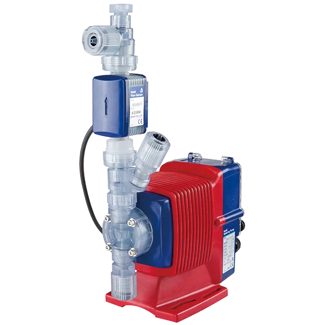
Discharge capacity range: 30 – 110 mL/min The Auto-air vent valve eliminates the gas-lock problem
※In order to download information materials and catalogues, you need to register a user
account (for free) with us. Membership Registration
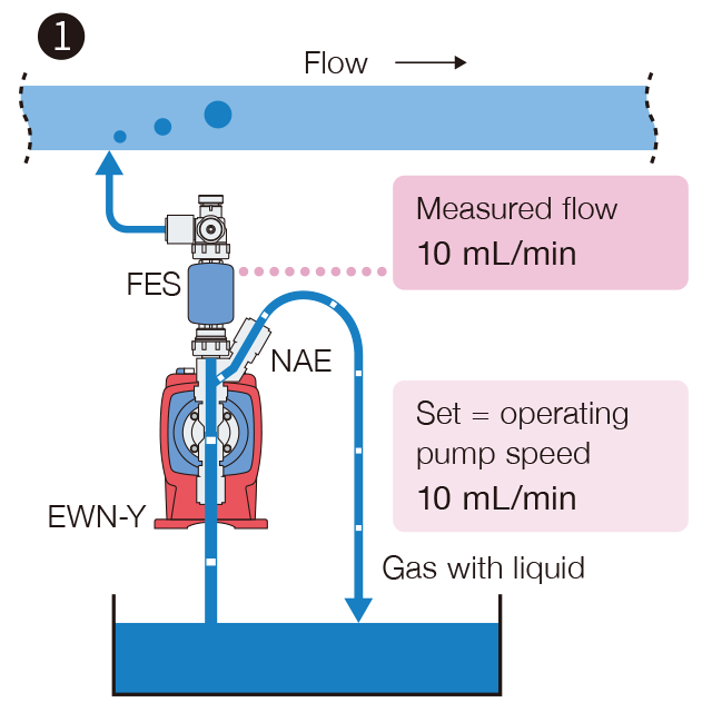
The bleeding system takes gas and liquid out from the pump chamber. However, dosing capacity is kept setting volume due to feed back control with the flow signal.
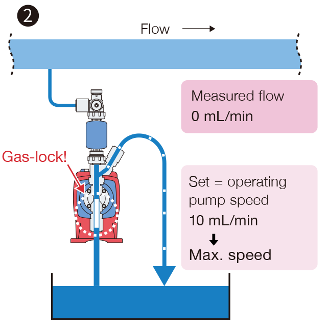
When large volume of gas comes into the pump chamber, pump discharge capacity will be “zero” until bleeding the gas out. The feed back control increase pump operating speed, thus gas bleeding time will be in short time.
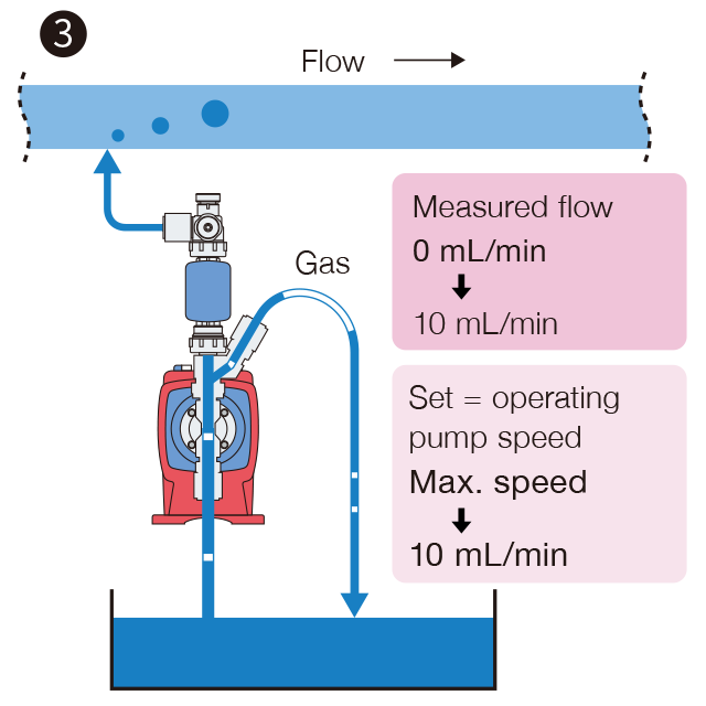
When the gas bleeding is completed, the pump discharge volume returns to the setting valve immediately by the feed back control with the flow signal.
| Discharge capacity range | 30 – 110 mL/min |
|---|---|
| Max. discharge pressure range | 0.7 – 1.0 MPa |
| Main materials | PVC, PTFE |
| Stroke rate | 1 – 360 spm |
| Liquid temperature range | 0 – 40°C |
| Viscous liquid | Please contact us for details. |
| Operation mode | MAN control | Operation at MAN speed | 0.1 – 100.0% (1 – 360 spm) |
|---|---|---|---|
| Feedback control | 0.1 – 999.9 mL/min, 0.001 – 59.994 L/H, 0.001 – 15.828 GPH | ||
| EXT control | ANA.R (analogue rigid) | 4 – 20, 20 – 4, 0 – 20, 20 – 0 mA (proportional operation with stroke rate) | |
| ANA.V (analogue variable) | 2 point setting (set point 1 and 2, flow rate or stroke rate) | ||
| BATCH (batch operation) | 0.1 – 99999.9 mL, 0.001 – 99.999 L, 0.001 – 26.385 G | ||
| PLS (pulse operation) | 2 point setting (set point 1 and 2, flow rate or stroke rate) | ||
| Input | Buffer pulse | No voltage contact or open collector | |
| Analogue | 0 – 20 mADC (input resistance 220 Ω) | ||
| STOP/Pre-STOP (level sensor) | No voltage contact or open collector | ||
| AUX | No voltage contact or open collector | ||
| Interlock | No voltage contact or open collector | ||
| Batch Start/Stop | No voltage contact or open collector | ||
| Pulse | No voltage contact or open collector | ||
| Output | OUT1 | No voltage contact (mechanical relay) 250 VAC at 3A (resistance load), Enable or disable the alarms of STOP, Pre-STOP, Interlock, Batch, Out of measurement and Poor flow | |
| OUT2 | No voltage contact (photoMOS) 24 VAC/DC at 0.1 A, Enable or disable the alarms of STOP, Pre-STOP, Interlock, Batch, Out of measurement and Poor flow or Synchronous output (sensor/pump) | ||
| Analogue | 4 – 20 mADC (The max. load resistance is 500 Ω) | ||
| Buffer memory | Nonvolatile memory | ||
| Power voltage | 100 – 240 VAC 50/60 Hz | ||
Kindly use this inquiry form for placing an order or sending your inquiry
about our fluid control devices including chemical pumps.
HomeP